3D SCANNING, DIGITIZATION
AND REVERSE ENGINEERING
“The 3D scanning of our prototype autogyro gave us a new direction in terms of design. It helped us define the real dimensions, uncover potential problems as well as the actual position of each component once they were assembled. It also helped us discover inaccuracies which affected its flight properties. We also used the scanned data to modify the moulds, thus reducing the whole production process of the production model by several weeks. The data obtained helped optimise the geometry of the undercarriage and the position and lift of the suspension. The quality, precision and detail of the scanned data enabled us to solve questions of aerodynamics, defining flight surfaces as well as the layout of the interior elements.”
Ondrej Jancovic
Director and Chief Designer, JOKERTRIKER s.r.o.

Industry: Aviation and mechanical engineering industry
Focus of activity: Custom and small-batch production of machined components for the mechanical engineering, automotive and aviation industry.
Location: JOKERTRIKE s.r.o., Slovakia
Asseco CEIT solution: 3D Scanning, Digitization, Reverse Engineering and Metrology
Bringing reality into the digital world
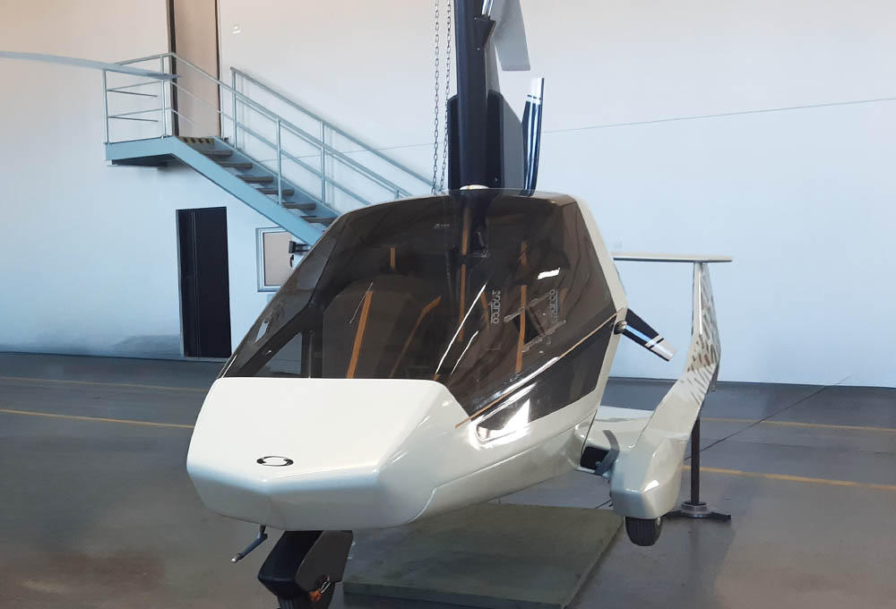
Standard product development uses a chronological approach, creating a computer model and drawing which then leads to a prototype with exact parameters. However, the small aircraft industry, as well as design itself, takes an opposite approach. A prototype model is made based on a design, experience and skills, and this is then adjusted during testing. In aviation, we use the term “it is learning to fly”. This is a complicated process, full of changes, resulting in a flying prototype which is quite different to the previous design. This was an ideal situation for putting reverse engineering into use. With the correct application of advanced reverse engineering technologies, it was possible to obtain a digital form of the flight prototype, to adapt its original designs and then to begin its serial production.
Steps performed and project output
- The template method was not suitable; a combination of 3D scanning and 3D measurements was used.
- The measurement was carried out using a 3D FARO Edge Scan ARM®HD scanner.
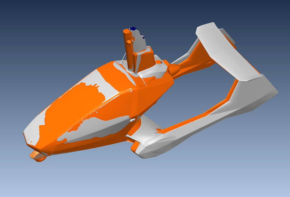
- The external airframe (fuselage, engine mounts), interior and fuel tank were scanned.
- After all the required parts were scanned, the moulds were scanned in order to find differences between the parts that come out of the moulds and the actual shape of the mould.
- Scanning of the outer surface and flight surfaces
- Scanning of the interior
- Scanning of the functional components
- Scanning of the prototype moulds
Project output
- Using contactless scanning, we obtained a very precise and detailed stereolytographic model (STL) of the surface and interior of the autogyro.
- Using a tactile probe, the assembly holes of the engine, undercarriage and key structural elements were precisely located.
- Editing the scanned data produces an approximate model (STEP) in a format boasting better compatibility with CAD systems.
- Based on the scanned data and the results of simulations from a virtual aerodynamic tunnel, the rear of the autogyro, the engine cover and the cabin shape were reworked. The bottom part of the fuselage and covers of the weight-bearing parts were reworked, as well as the cooling system, the elements of which were given a new place in the newly designed aerodynamic parts of the fuselage.
Thanks to the 3D data provided, JOKERTRIKE s.r.o. was able to continue developing its autogyro, and using the 3D data output was able to make its own adjustments and update its existing model in 3D data.
It is also thanks to Asseco CEIT that the NISUS AERO autogyro could be presented at the EXPO 2020 fair in Dubai.
Project in numbers:
total scanned surface area
16.9 m²
volume of the scanned body
2.5 m³
increase in speed
from 120 km/h to 140 km/h
fuselage resistance reduced by
18.1%
project duration
2 weeks

